Control Board Lab
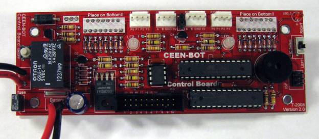
Top View
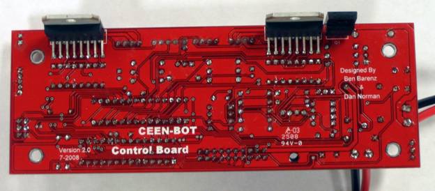
Bottom View
Open the bag of parts for the Control board and sort them onto the Parts Map. Do this before you solder any components to minimize the chance of misreading a component's id and soldering it into the wrong location. Solder the components in the order shown on the parts map. The order is basically that the lowest profile items are soldered first. The dashed outlines on the parts map indicate components that must be oriented a specific way. Do not solder the integrated circuit on the board. It is placed into a socket.
The techniques for soldering many of these components are the same as was done for the Interface board. References to video clips in that tutorial are given if you wish to review the procedure.
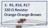
1. The first items to be soldered are resistors R5, R16, and R17. Orientation does not matter for resistors. (Video 2)
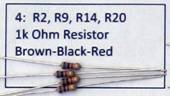
2. Next are resistors R2, R9, R14 and R20. Brown-Black-Red
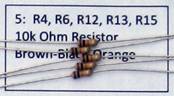
3. Resistors R4, R6, R12, R13, R15.
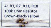
4. R3, R7, R11, AND R18
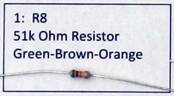
5. R8
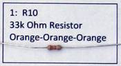
6. R10
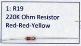
7. R19
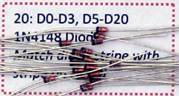
8. Diodes D0-D3, D5-D20. Align the black stripe on the diode with the white stripe on the circuit board. (Video 1)
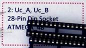
9. Uc_A and Uc_B Sockets. Align u shaped notch on end of socket. (Video 15)
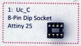
10. Uc_C Socket. Align u shaped notch on end of socket.
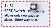
11. Switch 1
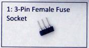
12. Fuse socket. Use machined female sockets.
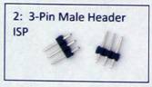
13. Solder the two 3-pin male header (Video 12)
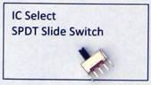
14. SPDT Switch
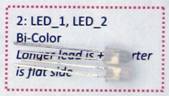
15. Bi Color LED Longer lead is +, shorter lead is negation and is placed by the flat side of the silk screen symbol.
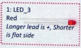
16. Red LED_3. Longer lead is +, shorter lead is negation and is placed by the flat side of the silk screen symbol.
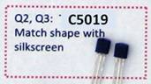
17. Q2, Q3. Match shape with silk screen. These look just like Q4. Read the numbers printed on them to make sure you have the correct devices.
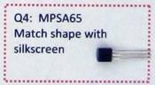
18. Q4. Match shape with silk screen. These look just like Q2 and Q3. Read the numbers printed on them to make sure you have the correct devices.
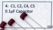
19. 0.1 uF Capacitors. Orientation not important.

20. D1 1N5402 Diode. Align the black stripe on the diode with the white stripe on the circuit board.
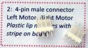
21. 4-pin male connector. Left Motor, Right Motor. Photo shows 4 - we will only use 2. Plastic lip matches with stripe on board.
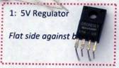
22. 5 Volt Regulator. Flat side against circuit board.
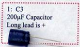
23. C3 200uF capacitor. Long lead is +.
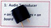
24. Audio Transducer. + on case matches + on board.
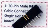
25. 20-Pin Male Ribbon Cable Connector. Single slot to center of board.
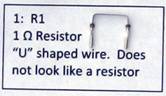
26. R1. 1 ohm Resistor. "U" shaped wire. Does not look like a resistor.
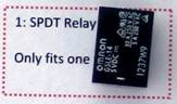
27. SPDT Relay. Pins will allow it to fit only one way.
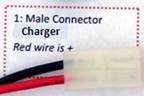
28. Male Connector. Battery. Red wire is +. Strip about 1/8" of insulation off wires. The male connector has two prongs inside the plastic case.
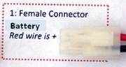
29. Female Connector. Charger. Red wire is +. Strip about 1/8" of insulation off wires. The female connector has two sockets inside the plastic case.
WARNING The following parts are mounted on the bottom side of the board. Look at the photo.
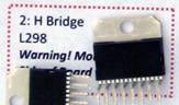
30. H Bridge. L298. Warning! Mount on Back Side of Board
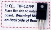
31. Q1. TIP-127FP. Place flat side to outside of board. Warning! Mount on Back Side of Board.
The following components are not soldered. They are placed in sockets. They may not be in your parts bag in which case they will be given to you after you have completed soldering.
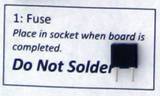
32. Fuse. Place in socket when board is completed. Do Not Solder.
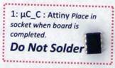
33. uC_C : Attiny Place in socket when board is completed. Do Not Solder. (Video 19)
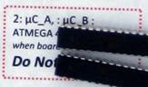
34. uC_A, : uC_B : ATMEGA 48 Place in socket when board is completed. Do Not Solder. (Video 19)